Skeleton Joint Changes Color
🔌dp.kinect dp.kinect2 dp.kinect3 dp.oak
Learn how to get the real-world XYZ position of your left hand relative to your sensor. Then, use that hand position to change the color of a panel.
📝 This tutorial uses the
dp.kinect2plugin. Substitute the name of your own sensor plugin. For example, if you have an OAK sensor, typedp.oakinstead.
- Create a new blank patch
- Create a dp.kinect2 object in your patch with the arguments
@skeleton 1 @skeletonformat 1. This instructs the dp.kinect2 object to output joint locations and to use a native Max message format for that data. OSC format data is also supported and is the default for backwards compatibility. - You should not have any red errors in your Max console window. You can view this console window using the Windows menu on the toolbar or pressing control+m. If you have errors, please refer to those errors and the setup guide for your plugin.
- Like many objects in Max, dp.kinect2 requires you to
bangthe first inlet to output data from it. If you are not familiar with this, please visit the Max jitter tutorials online or within Max. - Create a toggle object.
- Create a qmetro object with the argument
33. This instructs the qmetro to output a bang every 33 milliseconds (1/30th of a second). Why this interval? Because, the native framerate of most sensors is 1/30th of a second. - Connect the outlet of the toggle to the inlet of the qmetro.
- Connect the output of the qmetro to the inlet of the dp.kinect2 object.
- Create a message object and make its message
open. - Connect the output of the message object to the inlet of the dp.kinect2 object. The open message is needed to start/open a connection to your sensor.
- Create a route object with the argument
skel. dp.kinect2 can output many messages to provide you with the data you request. The messages with joint locations start withskel. - Connect the fifth outlet of dp.kinect2 to the first inlet of route.
- Create a zl object with the arguments
slice 1. The zl object has many features. We will use it to slice off and ignore the numeric playerId associated with all the data for a person. We do not need the playerId for this tutorial. - Connect the first outlet of route to the first inlet of zl.
- Create another route object with the argument
l_hand. This route object will be used to isolate and only pass the message for the left hand. If you prefer, you can user_handfor your right hand. - Connect the second outlet of zl to the first inlet of this new route object.
- Create a message object. This will be used to display the location of your left hand.
- Connect the first outlet of route to the second inlet of the message object. This second inlet will display whatever message you send it.
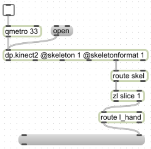
- Your patch should look similar to this picture
- Lock your patch to make it easier to interact.
- Click the open message. Click the toggle to turn it on. You should not have any red errors in your Max console window.
Stand in front of the sensor and move your hand.
Congratulations! 🎉 You should now see the real-world x, y, z position of your hand in meters
relative to the sensor. In the below picture, the hand is 0.26 meters to the left of the
sensor, 0.37 meters above the sensor, and 1.15 meters in front of the sensor.
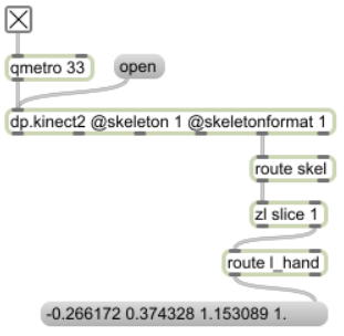
Look closely. There is a fourth number being output in that message. In the picture above
it is 1.. This last number represents the confidence in the x, y, z values. The confidence
can range from 0.0 to 1.0. A value of 1.0 is a very high confidence in the position values.
A confidence of 0.5 is a good guess at the position values. By default, you are provided
all data with a confidence of 0.5 or higher. You can change this with the
@posconfidence attribute. If you change it to 1.0,
then dp.kinect2 would only send you the very high confidence data and filter out the rest.
Let’s have some fun with 🎨 color. We will update this patch to control the hue and luminance of a panel using only your hand.
- Unlock your patch.
- Delete the message box at the bottom.
- Create a zl object with the arguments
slice 2. - Connect the first outlet of route to the first inlet of this zl object. This will slice the x, y, z, confidence message so that we only have the x and y values.
- Create a message object with the arguments
hsl $1 1. $2. - Create a swatch object.
- Create a prepend object with the argument
bgcolor. - Create a panel object.
- Connect zl -> message -> swatch -> prepend -> panel.
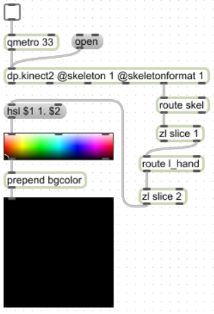
- Your patch should look similar to this picture
- Lock your patch to make it easier to interact.
- Click the open message and turn on the qmetro.
Fantastic! You can change the color of the panel with your hand directly in front of the sensor and moving it up one meter and to the right one meter.
In steps 3-10, we use the x and y values to create a new message starting with hsl.
The swatch object understands this as hue, saturation, and luminance. The swatch object
will show you a circle representing the current color and then send that color out its
first outlet. We then prepend bgcolor to that message which can then be understood
by the panel object.
When you want to learn more, please see the help file included with the plugin download. Each tab in the help file includes comments at key locations of the patch. Naturally, this documentation website is good for technical details.